5 Railway design
Description hierarchy
| Transfer file |
| Metric |
Coordinate and elevation system
|
Base point
|
| Project |
"IM_codings" extension
Type coding system
|
Application
|
Authors
|
| Alignment (one continuous stationed track) |
Alignment
|
| Geometry (according to the described item) |
| *1) |
Line (alignment) |
"IM_switch" extension
Track switch information |
| *2) |
Line string
|
| *1) |
Circular arc (alignment) |
| *1) |
Transition curve (alignment) |
Stationing for KM-posts
|
"IM_kmPostCoords" extension
Track km post coordinates (2D) |
Track parameters
|
Cant (Stationing reference track / track centerline)
|
| Design speed (Stationing reference track / track centerline) |
| Vertical profile (according to described item) |
Vertical geometry
|
| *1) |
Point of vertical intersection (alignment) |
| *1) |
Circular curve (alignment) |
Cross sections
|
Cross section
|
"IM_crossSect" extension (Stationing reference track)
cross-section parameters
|
"IM_coding" extension
type coding lines
|
"IM_stringlineLayers" extension
string line model
|
"IM_stringlineLayer" extension
string line model layer - lines and name of layer
|
"IM_coding" extension
type coding
|
"IM_plan" extensions
plan information
|
| Collection of railways |
| Individual railway |
| Planimetric feature such as building footprint, guard rail, lightpole or signage |
| Plan feature geometry |
| Line (geom. line) |
| Line string |
| Circular arc (geom. line) |
| Transition curve (geom. line) |
| Plan feature location |
plan feature details:
"IM_cable"
"IM_footing"
"IM_railing"
"IM_fence"
"IM_planfeature" |
"IM_coding" extension
type coding planfeature |
surface group
|
| surface |
Source data
|
breaklines
|
| breakline |
3D point list
|
"IM_coding" extension
type coding breakline
|
Data points
|
3D point list
|
"IM_coding" extension
type coding data points
|
Surface description
|
| Vertices |
| Vertex |
| Faces |
Face
|
"IM_coding"
extension
type coding surface
|
"IM_plan" extension
design information
|
Extension definitions
|
5.1 Contents
The methods used to describe a route in inframodel file transfer are described in detail in the section route planning. It is possible to describe road, street and railway plans and information about water supply and sewerage. A railway plan typically consists of one continuous track for KM-posting and other tracks. The centerlines and the bottoms of the rails of each track are described as geometric alignments. The transition points for cant and design speeds are also described in conjunction with the stationing of the centerlines of the KM-posting track and of other tracks. The current specification does not include description of switches and crossings. The alignments with string line representations can be collected into a string line model of the railway. The model can also include a surface model and structural model, and it is possible to attach additional breakline and random point information.
5.2 Track geometry
One <Alignments> collection containing several <Alignment> elements is used for describing a railway geometry. Only one of those <Alignment> elements can be the centerline of reference track for KM-posting. Description a track centerline is always a geometric <Alignment> (description hierarchy *1).
The geometric alignment description is composed of elements in horizontal and vertical geometry, respectively (see section 3.3). The KM-posting reference track and additional track center lines have their own type codes in inframodel rail planning. Other lines than centerlines and the bottoms of the rails are described as line strings (description hierarchy *2). Since the string line model of the track only uses line strings, the line information contained by the geometry lines is also described as an approximate line string. These may be presented in any order. The type coding of individual lines determines their purposes; the type code (terrainCoding) for the terrain model is set in a structural extension. The desired lines can be included in a string line model, according to the structural extension "IM_stringlineLayers". In the stringline model the surfaces can be assigned surface codes (surfaceCoding). The surface and structural models of a railway can also be described as triangular meshes (TIN surfaces). The raiway plan information is defined in the optional "IM_plan" structural extension.
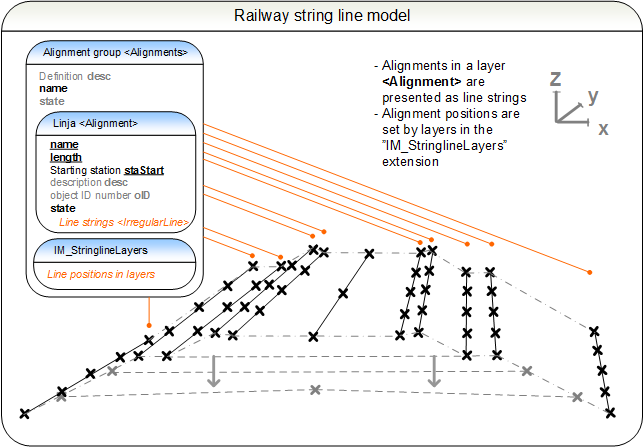
5.3 String line model
After a particular <Alignment> out of a group of <Alignments> has been defined, the stringline model may be defined in the structural extension "IM_stringlineLayers". The mode of presentation is akin to cross-sections, the stringline layers of the string line model are refered to by their name <Alignment>.name
and the location is described as surfaces. It is not always possible to present all line strings contained by the layer in order from left to right, although this is recommended.
The detailed description of the construction process of line string model can be found in section 3.5. The lines of the string line model employ the same terrain point coding as alignments. Surfaces are defined in the string line model with surface codes (surfaceCoding).
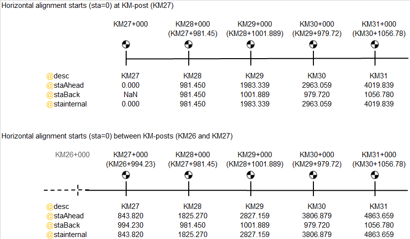
5.4 KM-posting
The KM-posting method in inframodel uses <StaEquation> in a way that somewhat differs from its typical use in LandXML. The individual km-post station distances from the previous post station are defined by their back stations staBack (for the first KM-post on a given alignment, the staBack can be set to "NaN", when it is not known or relevant). This use of <StaEquation> does not imply a re-start in the alignment stationing, hence in inframodel the staAhead attribute is always set to the same value as staInternal attribute. Individual locations according to the KM-posting system on all tracks are presented in relation to the KM-posting reference alignment. The name of the KM-post station is defined by the desc attribute.
Although the Finnish KM-posting system is nominally kilometre based, it cannot be used to define distances between points. The actual length of a track is therefore calculated along the centerline <Alignment> of that track, resulting in continuous internal stationing in staInternal attribute values.
The <StaEquation> attributes:
 |
staAhead |
the "new" station value
|
e.g. [2963.059] |
|
staBack |
distance to previous km-post station
|
e.g. [979.720000] |
|
staInternal |
internal stationing
|
e.g. [2963.059] |
|
desc |
description |
esim. [KM30] |
"IM_kmPostCoords" <Feature>
 |
|
<StaEquation> |
schema documentation |
 |
|
<StaEquation> |
short example |
5.5 Cross-sections and track information
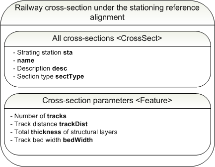
Cross-section plan contains information that fleshes out the geometry and string line model descriptions of the railway. The information contained by the cross-section element is valid from the given station forward, either to the next transition cross-section element or the end of the line. The cross-section parameters are described under the KM-posting reference track in the <Alignment>.<CrossSects>.<CrossSect> element and its extension "IM_crossSect" (<Feature>).
It is recommended that all parameters are described along with the cross-section. Details on the Finnish railway design parameters are provided by Finnish Transport Infrastructure Agency (FTIA).
5.5.1 Cross-sections
The cross-sections for KM-posting reference track are defined by the element <Alignment>.<CrossSects>.<CrossSect>. For individual cross-sections, the cross-section parameters are presented in the extension "IM_crossSect". Transitions are defined in the points where parameters change start and where they have reached their final values after the transition. Triple and higher multiple track railways are composed of double and single track standard cross-sections.
Cross section <CrossSect> attributes
|
|
<CrossSects> |
schema documentation |
|
|
<CrossSect> |
schema documentation |
The following information must be defined in the extension "IM_crossSect" for an individual cross-section:
- the number of tracks tracks
- the distance between track centerlines trackDist
- the total thichness of track bed layers thickness
- track bed or cut width bedWidth
"IM_crossSects" <Feature>
|
|
<Feature> |
schema documentation |
|
|
<Feature> |
short example |
5.5.2 Track information
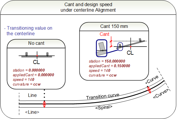
The transitions in cant and design speed for each track are described under the track centerline <Alignment> in <Cant> sub-elements. The track information <Cant> defines the name, the track gauge and the cant rotation point rotationPoint.
|
|
<Cant> |
schema documentation |
|
|
<Cant> |
short example |
The following transitions are described by the track information sub-element:
 <CantStation> is used at cant events, typically: 0-value at the start and end of straight track segments, same value at the start and end of circular curve segments, and different values at start and end of transition curve segments (interpolated according to the horizontal spiral curvature change)
<SpeedStation> is used when the design speed changes
1) When the cant changes in the <CantStation>:
|
|
<CantStation> |
schema documentation |
|
|
<CantStation> |
short example |
2) When the design speed changes in the <SpeedStation>
|
station |
design speed change station |
e.g. [150.000000] |
|
speed |
design speed |
in file velocity units, e.g. [160] |
|
|
<SpeedStation> |
schema documentation |
|
|
<SpeedStation> |
short example |
5.5.3 Switch information
The information on switches of tracks is given under track centerlines in the <Alignment>.<CoordGeom>.<Line> using "IM_switch" <Feature>
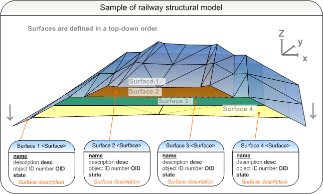
5.6 Terrain model and structural model of the track
The presentation method of the terrain model is described in further detail in the section 3.6 Terrain model. The terrain model of the track only contains the triangular mesh surface of the visible track structures. The structural model contains all surfaces as described in 3.7 Structural model. The goal is to assign all surfaces a type code in accordance to the type coding system.
It is also possible to add source data point and breakline information to surfaces. This is described in further detail in the section 2.3 Source data.
5.7 Rail plan features
The rail planimetric features such as fences, lightpole or signage footings that are assigned to a particular railway are described under roadways. A roadways collection <Roadways> may consist of several roadway <Roadway> elements. Each roadway has a reference to its centerline <Alignment>, and it can hold a number of <PlanFeature> elements.
Attributes of the roadways collection <Roadways> are not used in inframodel.
Attributes of a roadway <Roadway>:
|
name |
unique name |
e.g. [R001]
Note: this shall match the Alignments@name of the alignment group where the alignment referenced by alignmentRefs is found |
|
alignmentRefs |
reference to Alignment@name |
e.g. [001] |
 |
desc |
description |
e.g. [Railway R001 signage footing plans] |
|
state |
state |
[abandoned]
[destroyed]
[existing]
[proposed] |
5.7.1 Plan features
The individual plan features are each described under <PlanFeature>, having a mandatory and unique name and optionally <Location> and geometry as <CoordGeom>.
Attributes of <PlanFeature>:
|
desc |
description |
e.g. [Steel mesh fence] |
|
name |
unique name |
e.g. [f_123] |
|
state |
state
|
[abandoned]
[destroyed]
[existing]
[proposed] |
<PlanFeature> geometry is described in <CoordGeom> using line strings for linear features, e.g. cables, railings and fences. For point features, such as footings, location is given in <Location> element as a two or three dimensional point:
<Location>northing easting (elevation)<Location>
Details of <PlanFeature> are described as <Feature> extension, defined for each type as follows:
Additionally, all plan features may be type coded in <Feature> using 7. Type coding in "IM_coding" extension.