3 Route planning
Description hierarchy
Transfer file
|
| Units (Metric) |
Coordinate and elevation system
|
Base point
|
| Project |
"IM_codings" extension
Type coding system
|
Application
|
| Authors |
| Alignment (one continuous stationed track) |
Alignment
|
| Geometry (according to the described item) |
| *1) |
Line (horizontal geometry) |
| *2) |
Line string
|
| *1) |
Circular arc (horizontal geometry) |
| *1) |
Transition curve (horizontal geometry) |
| Vertical profile (according to described item) |
Vertical geometry
|
| *1) |
Point of vertical intersection (vertical geometry) |
| *1) |
Circular curve (vertical geometry) |
"IM_coding" extension
type coding
|
"IM_stringlineLayers" extension
string line model
|
"IM_stringlineLayer" extension
string line model layer - lines and name of layer
|
"IM_coding" extension
type coding
|
"IM_plan" extension
plan information
|
surface group
|
| surface |
Source data
|
breaklines
|
| breakline |
3D point list
|
"IM_coding" extension
type coding breakline
|
Data points
|
3D point list
|
"IM_coding" extension
type coding data points
|
Surface description
|
| Vertices |
| Vertex |
| Faces |
Face
|
"IM_coding" extension
type coding surface
|
"IM_plan" extension
design information
|
Extension definitions
|
3.1 Contents
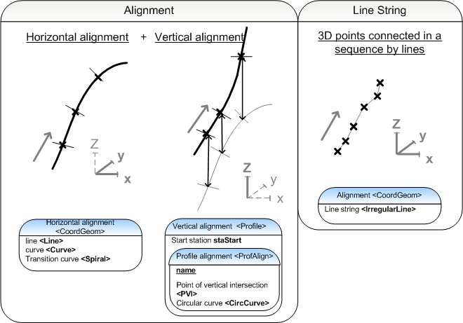
Routes encompass highways, local roads and private roads, waterways and railways. Each route has one continuous stationing reference alignment and a vertical alignment. In inframodel file transfer, a route plan consists of parametric route alignments, their stringline models and surface models as triangulated meshes.
An alignment group <Alignments> consists of several alignments <Alignment>. Surfaces can be described in two ways:

Geometric alignment (
see hierarchy *1)
Line string (
see hierarchy *2)
Geometric alignments describe parameters of the horizontal and vertical elements of an alignment. A line string is a description where consequtive points are connected by line
segments. Geometric alignments are typicaly used to describe the reference line of a road as well as other important geometric descriptions such as road edges. Other route components are usually described as line strings.
Once the alignments have been described, it is possible to assign them to a line string model, that contains a description of the layers of the route structure. Alternatively, a surface model of the route is a triangular mesh representation of the surface structure of the route. The structural model describes all the layers in a route structure as triangle mesh surfaces.
Cross-sectional parameters, which are described in further detail in the sections covering each route type, complement the route description with parametric information of the cross-sections (without actual cross section geometry).
Route description
Route description is driven by stationing reference line (principal alignment). Other geometry lines are given in the same alignment collection <Alignments> each as separate alignment <Alignment>. Geometry lines and stringlines are given in separate alignment collections <Alignments>.
Different routes, alignement options and stationing reference line discontinuities are placed in separate<Alignments>.
Naming and Type coding
Alignment groups and each individual alignment within a group must be assigned unique name. It is advisble to assign different names to geometric alignments and line strings in string line models. Assigning type codes to alignments is optional in Inframodel file transfers. An <Alignment> may assigned a type code as explained in 3.2.2 Type coding. Layers of string line model of the route, described in optional "IM_stringLineLayers" extension may also have type codes.
3.2 Composing alignments
The names name of alignment groups <Alignments> are unique. The state attribute is optional. The description attribute desc is also optional and may be used to describe the alignment group <Alignments> in further detail.
Attributes of an alignment group <Alignments>:
 |
desc |
description |
e.g. [Route E18 plan, interval X - Y] |
 |
name |
name |
e.g. [E18] |
|
state |
state
|
[abandoned]
[destroyed]
[existing]
[proposed] |
 |
|
<Alignments> |
schema documentation |
An <Alignment> is an element that describes 1) a geometric alignment or 2) a line string. The alignments within a file do not have to be presented in any particular order. It is, however, advisable to first describe geometric alignments and then line strings. The <Alignment> definition describes a name, length, the stationing start staStart and the state of the <Alignment>. It is recommended that lines are named in an intuitive fashion. If the state is set for the entire alignment group <Alignments> the <Alignment> elements will inherit the state attribute from the parent element, hence is should not be set. When alternative alignments are being described by different alignment groups the differences between elements can be described briefly in the atrribute desc. The optional object identifying number oID makes object management easier in applications.
Attributes of an <Alignment>:
|
name |
name |
e.g. [stationing reference line] |
|
length |
length
|
in distance units, e.g. [2768.500000] |
|
staStart |
start station
|
e.g. [0.000000] |
|
desc |
description |
e.g. [continuous] |
|
oID |
object ID number |
individual identifier within the file, e.g. [1] |
|
state |
state
|
[abandoned]
[destroyed]
[existing]
[proposed] |
A geometric alignment contains a horizontal geometry in a <CoordGeom> element and the corresponding vertical alignment in a <Profile>.<ProfAlign> element. Line strings are described as a chain of 3D points in the <CoordGeom> element. The purpose of the alignments is defined by a type code.
|
|
<Alignment> |
schema documentation |
 |
|
<Alignment> |
short example |
3.2.1 Plan information
The plan information of an alignment group is described under the <Alignments>
element in the optional extension "IM_plan". If the plan consists of
subsets that progress at a different rate or there is some other reason
to partition the project into smaller entities, these subsets should be sorted into separate alignment groups. The plan information contains information about the planName, the planCode, the planState and a description of the plan, planDesc. The state is described accrding to a system agreed on by the parties of the project. See sample in the table below. The plan information is also set when describing the surfaces of a route. These are set in the "IM_plan" extension of the <Surfaces> element.
Plan information "IM_plan"
<Feature>
|
name |
optional name
|
e.g. [5] |
|
code |
code
|
[IM_plan] |
|
source |
source
|
[inframodel] |
|
label |
[planName] |
plan name
|
value |
e.g. [plan2] |
|
label |
[planCode] |
plan code
|
value |
e.g. [12345-322] |
|
label |
[planState] |
plan state
|
value |
agreed on by the parties, e.g. [zoning | preliminary plan | general plan | plan | construction plan | construction | maintenance | removal] |
|
label |
[planDesc] |
plan description
|
value |
additional information, e.g. [part1] |
|
label |
[planType] |
type of planned alignment
|
value |
[road | railway | waterway | other] |
|
|
<Feature> |
schema documentation |
3.2.2 Type coding
The type coding systems of an <Alignment> are defined in the project information. The type coding is set for each <Alignment> element, whose children inherit the values. The type code of an <Alignment> is set in the extension "IM_coding" with the infraCoding and its description infraCodingDesc. This documentation discusses individually different route types: 1) roads and streets 2) railways 3) waterways.
The string line model is described in the extension "IM_stringLineLayers" (after the individual alignments); the description procedure is explained in further detail in section 3.5 String line model. The line strings of the string line model are grouped into layers that are type coded using the surface model type codes surfaceCoding and its description surfaceCodingDesc.
Inframodel exchange uses the general InfraBIM type coding [InfraBIM] for both alignments and string line models.
Alternative type coding systems can be set using e.g. name proprietaryInfraCoding and description proprietaryInfraCodingDesc.
"IM_coding" <Feature> under an <Alignment>:
|
name |
optional name |
e.g. [6] |
|
code |
code |
[IM_coding] |
|
source |
source
|
[inframodel] |
|
label |
[infraCoding] |
alignment code
|
value |
code, e.g. [101] |
|
label |
[infraCodingDesc] |
description of the alignment code
|
value |
description, e.g. [Mittalinja] for stationing reference line |
|
label |
[surfaceCoding] |
surface code
|
value |
code, e.g. [214111] |
|
label |
[surfaceCodingDesc] |
description of the surface code |
value |
description, e.g. [Top of Pavement] |
|
label |
[proprietaryInfraCoding] |
optional or internal coding |
value |
proprietary code
e.g. [x:111]
e.g. [y:132] |
|
label |
[proprietaryInfraCodingDesc] |
description of optional or internal coding |
value |
description
e.g. [Other road breakline]
e.g. [Bottom of ditch] |
|
|
<Feature> |
schema documentation |
"IM_coding" <Feature> of a line string model:
|
name |
optional name |
e.g. [7] |
|
code |
code |
[IM_coding] |
|
source |
source
|
[inframodel] |
|
label |
[infraCoding] |
alignment code
|
value |
code, e.g. [121] |
|
label |
[infraCodingDesc] |
description of the alignment code
|
value |
description, e.g. [Keskilinja] for road centerline |
|
label |
[surfaceCoding] |
surface code
|
value |
code, e.g. [214111] |
|
label |
[surfaceCodingDesc] |
description of the surface code |
value |
description, e.g. [Top of Pavement] |
|
label |
[proprietaryInfraCoding] |
optional or internal coding |
value |
proprietary code
e.g. [x:111]
e.g. [y:132] |
|
label |
[proprietaryInfraCodingDesc] |
description of optional or internal coding |
value |
description
e.g. [Other road breakline]
e.g. [Bottom of ditch] |
3.3 Geometric alignments
The geometric alignment contains the horizontal and vertical alignment information. The horizontal alignment information is described in the <CoordGeom> and the corresponding (0 or 1) vertical geometry in the element <Profile>.<ProfAlign>. For the connection between horizontal and vertical geometry it is crucial that the geometric description is continuous from the beginning of the first element to the end of the last element. The horizontal geometry is described using a 2D coordinate representation, and the final elevation values along the element can only be produced once the vertical geometry is finished. The illustration below shows the horizontal and vertical geometry definition and their connection principal, the optional staStart attribute in <Line>, <Curve>, <Spiral> and <Profile> SHALL NOT be used for calculating horizontal or vertical geometry.

3.3.1 Horizontal geometry
The dimensioning components of horizontal alignments:
The horizontal alignment is a listing of consecutive dimensioning components, starting at the staStart of the parent <Alignment>. The precise location of the elements is defined in terms of 2D coordinates.
inframodel does not use attributes for the <CoordGeom> element.
|
|
<CoordGeom> |
schema documentation |
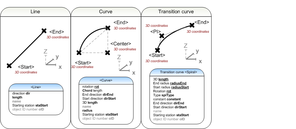
3.3.1.1 Line
A <Line> is defined by <Start> and <End> 2D coordinates (3D definition of is possible, but should not be used in horisontal alignment definitions). In addition, attributes direction dir and length are mandatory, but shall be used as additional information only.
1) Attributes of a <Line>:
|
dir |
direction
|
zero = north, in terms of direction units
|
|
length |
length |
in terms of length units
|
|
name |
name
|
according to the preferred element naming convention e.g.[line1] |
|
staStart |
starting station
|
informative line element start station value
|
|
oID |
object ID number |
individual identifier within the file, e.g. [2] |
2) The format for the <Start> and <End> coordinates of a <Line>, the 2D coordinates are separated by spaces.
<Start>northing1 easting1</Start>
<End>northing2 easting2</End>
|
|
<Line> |
schema documentation |
|
|
<Line> |
short example |
3.3.1.2 Curve
A circular arc <Curve> is defined by <Start> <Center> and <End> 2D coordinates (3D definition of is possible, but should not be used in horisontal alignment definitions). In addition, attributes direction of rotation rot, chord, end direction dirEnd, start direction dirStart, length and radius are mandatory, but shall be used as additional information only.
1) Attributes of a <Curve>:
|
rot |
direction of rotation |
clockwise / counter-clockwise [cw | ccw] |
|
chord |
length of the chord
|
in distance units
|
|
dirEnd |
end direction |
zero = north, in terms of direction units |
|
dirStart |
start direction |
zero = north, in terms of direction units |
|
length |
3D length |
in distance units |
|
name |
name |
according to preferred naming convention e.g.[Circular arc1] |
|
radius |
radius |
in distance units |
|
staStart |
starting station |
informative circular curve arc element start station value
|
|
oID |
object ID number |
individual identifier within the file, e.g. [3] |
2) The <Start>, <Center> and <End> of a <Curve>, the 2D coordinates are separated by spaces.
<Start>northing1 easting1</Start>
<Center>northing2 easting2</Center>
<End>northing3 easting3</End>
|
|
<Curve> |
schema documentation |
|
|
<Curve> |
short example |
3.3.1.3 Transition curve
A <Spiral> is defined by <Start>, point of intersection of the end tangents <PI> and <End> 2D coordinates (3D definition of is possible, but should not be used in horisontal alignment definitions), together with mandatory attribute transition curve type spiType. In addition, attributes length, end radius radiusEnd, start radius radiusStart, direction of rotation rot, the transition curve parameter constant, end direction dirEnd and start direction dirStart are mandatory. In Finnish route design the default transition curve type is an Euler spiral "clothoid"; bi-quadratic parabola "biquadraticParabola", or third-degree spiral "cubic" may be used under special circumstances e.g. in railway design.
1) attributes of a transition curve:
|
length |
3D length |
in distance units |
|
radiusEnd |
end radius |
in distance units, infinite = INF. e.g. [INF] |
|
radiusStart |
start radius |
in distance units, infinite = INF. e.g. [INF] |
|
rot |
direction of rotation |
clockwise / counter clockwise [cw | ccw] |
|
spiType |
type |
[clothoid | biquadraticParabola | cubic] |
|
constant |
parameter constant
|
|
|
dirEnd |
end direction |
in direction units, zero = north
|
|
dirStart |
start direction |
in direction units, zero = north |
|
name |
name |
according to preferred naming convention e.g.[klotoidi1] |
|
staStart |
starting station |
informative transition curve element start station value
|
|
oID |
object ID number |
individual identifier within the file, e.g. [4] |
2) The <Start>, point on intersection of start and end tangents <PI> and
<End> are defined as 2D coordinates separated by spaces.
<Start>northing1 easting1</Start>
<PI>northing2 easting2</PI>
<End>northing3 easting3</End>
|
|
<Spiral> |
schema documentation |
|
|
<Spiral> |
short example |
3.3.2 Vertical geometry
The vertical geometry is described in the <Profile>.<ProfAlign> element in concert with the horizontal geometry. In Inframodel, each horizontal geometry can have only one (or 0) vertical geometry. The dimensioning components of the vertical geometry are:
Point of Vertical Intersection
<PVI> Vertical circular arc <CircCurve>
The starting station staStart is an optional attribute of the vertical <Profile>.
|
staStart |
starting station |
|
|
|
<Profile> |
schema documentation |
|
|
<Profile> |
short example |
The name of the vertical geometry <ProfAlign> is a mandatory attribute:
|
name |
name |
|
|
|
<ProfAlign> |
schema documentation |
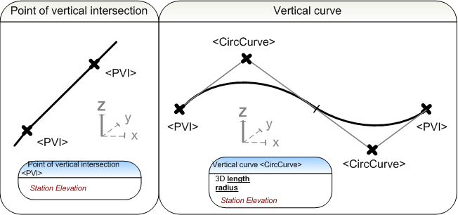
3.3.2.1 Point of vertical intersection
The first and last element of the vertical profile is always a Point of Vertical Intersection <PVI>.
A Point of Vertical Intersection <PVI> marks the ends of the line segments of a vertical geometry. A Point of Vertical Intersection is described by a station and an elevation. These are separated by a space.
<PVI>
station elevation</PVI>
The
<PVI> has the attribute
description desc.
|
desc |
description |
|
|
|
<PVI> |
schema documentation |
3.3.2.2 Vertical curve
Vertical circular arcs may be combined into S-curves or compound curves. The first and last element of a vertical profile is never a vertical circular arc
<CircCurve>.
The location of the <CircCurve> is defined by the station
ja elevation, separated by spaces.
<CircCurve length="length" radius="radius">station elevation</CircCurve>
The mandatory parameters of a verical circular arc are 3D length length and radius radius.
|
length |
3D length |
in distance units |
|
radius |
radius |
in distance units,
negative (-) when center of the circle is below the curve, e.g. [-100.000000]
positive (+) when center of the circle is above the curve, e.g. [98.500000] |
|
|
<CircCurve> |
schema documentation |
3.4 Line strings
Line strings are defined in concert with the horizontal geometry <CoordGeom>. Line strings are defined as a series of 2D points (when 2D representation is sufficient) or 3D points, hence it does not need a vertical <Profile> element for 3D representation. The dimensioning element of a line string is:
<
IrregularLine>
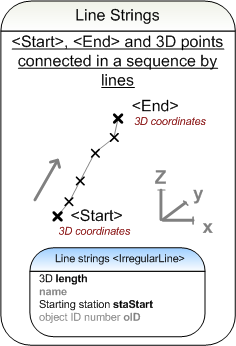
3.4.1 Line string
A line string has optional attributes and sub-elements to define its <Start>, <End> and the intermediate points either as <PntList2D> or <PntList3D>.
1) Attributes of the <IrregularLine>:
|
length |
length
|
in distance units |
|
name |
name |
e.g.[stringline1] |
|
staStart |
starting station |
|
|
oID |
object ID number |
individual identifier within the file, e.g. [5] |
2) The <Start> and
<End> points of an <IrregularLine>: individual coordinates are separated by spaces.
<Start>northing1 easting1 (elevation1)</Start>
<End>northing2 easting2 (elevation2)</End>
3a) The 2D point list <PntList2D>, consists of 2D coordinates of intermediate points and start and end points, separated by spaces.
<PntList2D>northing1 easting1 northing3 easting3 northing4 easting4...northing2 easting2</PntList2D>
3b) The 3D point list <PntList3D>, consists of 3D coordinates of intermediate points and start and end points, separated by spaces.
<PntList3D>northing1 easting1 elevation1 northing3 easting3 elevation3 northing4 easting4 elevation4...northing2 easting2 elevation2</PntList3D>
|
|
<IrregularLine> |
schema documentation |
|
|
<IrregularLine> |
short example |
3.5 String line model
An alignment group <Alignments> is a collection of geometric alignments and line strings. The string line model of a route is composed of their descriptions in the file, ordered into layers. The order of alignment descriptions within the alignment group does not matter. The string line model used in Inframodel is based on the Leica RoadRunner software.
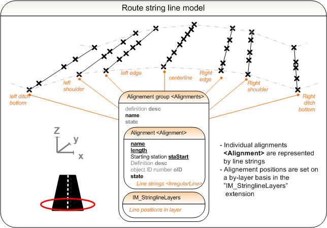
The string line model of a <Alignment> is defined by the "IM_stringlineLayers" extension. The string line model consists of individual line strings, whose locations are described layer by layer in the "IM_stringlineLayer" child element. The order of the <Alignment> elements is irrelevant, because their unique names are used as alignment identifiers <Alignment>.name. Each layer of the string line model is assigned a unique name and the alignments it contains. It is optional to define a centerline and set the surface codes surfaceCoding.
The procedure for constructing a new layer in the string line model in the "IM_stringlineLayers" extension goes as follows:
1) The layer is assigned a unique name.
2) The constituent line string alignments are selected by addressing the line strings by their name <Alignment>.name going from the left to the right. The line names are separated by commas.
4) The centreline may optionally be set.
5) The surfaceCoding and surfaceCodingDesc may optionally be set.
A line string may belong to several different layers. It is recommended to describe the layers in order beginning from the topmost layer. The string line model sample below utilizes the general surface coding. The sample describes a road surface and the underside of the lowest structural layer.
"IM_stringLineLayers" <Feature>
|
name |
optional name |
e.g. [8] |
|
code |
code |
[IM_stringlineLayers] |
|
source |
source |
[inframodel] |
"IM_stringLineLayer"
<Feature> - Layer 1 of the line string model
|
|
|
name |
optional name |
e.g. [9] |
|
|
code |
code |
[IM_stringlineLayer] |
|
|
source |
source |
[inframodel] |
|
|
label |
[name] |
name of the layer
|
value |
e.g. [roadway] |
|
|
label |
[alignments] |
alignments of the layer, left to right
|
value |
e.g. [LeftEdge,stationing_reference_line,RightEdge] |
|
|
label |
[centreline] |
centerline of the layer
|
value |
e.g. [stationing_reference_line] |
| "IM_coding" <Feature> |
|
|
name |
optional name |
e.g. [10] |
|
|
code |
code |
[IM_coding] |
|
|
source |
source |
[inframodel] |
|
|
label |
[surfaceCoding] |
surface code |
value |
surface system code,
e.g. [214111] |
|
|
label |
[surfaceCodingDesc] |
description of the surface code |
value |
description of the surface system code,
e.g. [Top of Pavement] |
| "IM_stringLineLayer"
<Feature> - Layer 2 of the line string model |
|
|
name |
optional name |
e.g. [10] |
|
|
code |
code |
[IM_stringlineLayer] |
|
|
source |
source |
[inframodel] |
|
|
label |
[name] |
name of the layer |
value |
e.g. [underside of the structure] |
|
|
label |
[alignments] |
alignments of the layer, left to right |
value |
e.g. [LeftEdge_underside,stationing reference line_underside,RightEdge_underside] |
|
|
label |
[centreline] |
centerline of the layer |
value |
e.g. [stationing_reference_line_base] |
| "IM_coding" <Feature> |
|
|
name |
optional name |
e.g. [10] |
|
|
code |
code |
[IM_coding] |
|
|
source |
source |
[inframodel] |
|
|
label |
[surfaceCoding] |
surface code |
value |
surface system code,
e.g. [15] |
|
|
label |
[surfaceCodingDesc] |
description of the surface code |
value |
description of the surface system code,
e.g. [Pavement] |
|
|
<Feature> |
schema documentation |
|
|
IM_stringLineLayers |
short example |
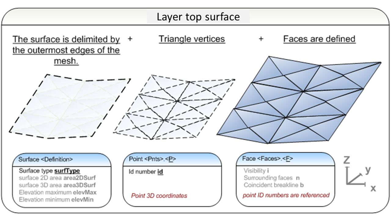
3.6 Terrain model
The route terrain model (<Surfaces>) contains a description of the topmost surface (one or more <Surface>) of the route (Digital Elevation Model). It consists of the vertices of the component faces <Pnts> and the faces <Faces> as explained section 2.3. Also, random points and breaklines of the surface can be described as explained in section 2.2. The route terrain model shall have the same name as the route alignments group, i.e. <Surfaces>.name shall match the corresponding <Alignments>.name
The route terrain model consists of:
Triangle vertices and
Faces,
Random points and
Breaklines,
Inframodel
type coding.
|
|
<Surfaces> |
schema documentation |
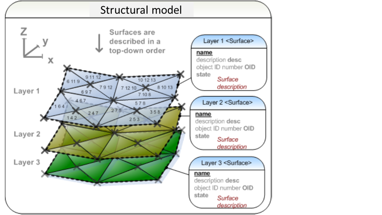
3.7 Structural model
The structural model of a route contains the surface meshes of all structural layers. When several layers are transferred in the same file, they shall be described in order from top to down, as explained in in section 2.5 Ground layer model.
|
|
<Surfaces> |
schema documentation |
3.8 Cross-section parameters
Cross-section parameters refer to parametric information complementing the model represented as surface or stringline models. These include design parameters such as the widths and superelevations of roads.
The relevant cross-section parameters for each route type are described in further detail in the corresponding section of each route type.