8 Water supply and sewerage
Description hierarchy
Transfer file
|
| Units (set for pipe networks) |
Coordinate and elevation systems
|
Base point
|
| Project |
"IM_codings" extension
type coding systems
|
| Application |
| Authors |
Pipe network group
|
Pipe network
|
Structure group
|
| Structure |
| Center, 2D |
|
|
 |
Circular structure
|
Rectangular structure
|
Pipe inlet
|
Pipe outlet
|
Pipe connection, joint or point of intersection
|
| Invert |
"IM_struct" structural extension Structure details
|
"IM_coding" extension Structure coding
|
Pipe group
|
| Pipe |
|
|
|
| Circular pipe |
| egg-shaped pipe |
| elliptic pipe |
| Rectangular pipe |
Channel
|
"IM_pipe" extension pipe details
|
"IM_coding" extension Pipe coding
|
Center, 3D, arcing pipe
|
"IM_pipeNetworkType" extension
labels for Inframodel extended network types
|
"IM_plan" extension plan details
|
| extension descriptions |
8.1 Contents
The drainage plan can be described in the same LandXML file as the rest of the plan content. The units used in drainage planning are the metric units and coordinate systems defined in chapter 1 Headers. If the drainage system utilizes coordinate or unit systems that differ from the rest of the it should be described as a separate LandXML file.
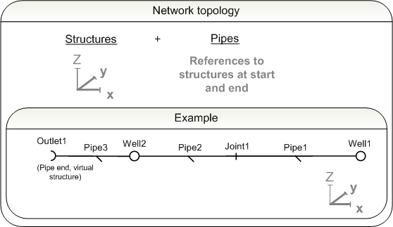
The drainage network in the LandXML standard is a topological one. The drain wells are nodes and the pipes are edges that connect these nodes. The model provides limited tools to design drainage, sewerage and water supply networks. inframodel file transfers have mandatory, optional and optional description elements. The following network types are implemented in the standard: storm drain, combined sewer, sewer, French drain, culvert, water pipe and "other", allowing the use of "IM_pipeNetworkType" extension for other types of networks, currently district heating, district cooling, gas and waste disposal.
Structures, such as different kind of drain wells are nodes. Pipes are defined as situated between two nodes. The ends of the pipes are modelled as virtual structures, of which there are two types, inlets and outlets. the LandXML standard supports a limited number of different structure and pipe types. Elements of Finnish design standards have been implemented in inframodel file transfers by adding extensions that expand on the LandXML element definitions.
The network topology is presented in the parent element <PipeNetworks> whose child elements are individual <PipeNetwork> elements. A <PipeNetwork> consists of structures and pipes.
 Structures
<
Structs>
- types: round and rectangular wells, virtual structures, equipment and pipe joints, extensions and inflexions. (see
description hierarchy *1)
- are given an exact location
- the pipe inlet is an <
Invert>
Pipes
<
Pipes>
- types: Circular pipe, elliptic pipe,
egg-shaped pipe, rectangular pipe and through (see
description hierarchy *2)
- are given a relative location - the ending and starting structures are named
-
the definition length is given as the distance between the centers of the terminal structures in the elevation of the inverts.
- the exact length may be described in the extension "IM_pipe" as a length attribute or as the arithmetic distance between the end coordinates of the pipe.
- pressurized sewers: described in the inframodel extension "IM_pipe" in an attribute.
The pipe network is, depending on the situation, usually described in its entirety. LandXML file transfers does not allow you to delimit the network without adhereing to the syntax. E.g. describing the inverts of the delimiting storm drain requires additional pipes and corresponding terminal structures. The process of delimiting the network is described in further detail in sections 8.5 and 8.6.
8.2 Pipe networks
A file may contain multiple pipe network groups <PipeNetworks>. It is mandatory to define the name of the pipe network and optional to give a description desc and state of the plan.
The pipe network groups are assigned unique names. If the network group contains networks with several different states, the state is not set.
Attributes of the Pipe network group <PipeNetworks>:
 |
desc |
description |
e.g. [plans] |
 |
name |
unique name |
e.g. [Example1] |
|
state |
state |
[abandoned]
[destroyed]
[existing]
[proposed] |
 |
|
<PipeNetworks> |
schema documentation |
8.2.1 Plan information
The plan information of the drainage plan is set in the optional "IM_plan" extension of the <PipeNetworks> element. If the project consists of several sub-entities, which progress at a different rate, the plan content should be divided into several network group <PipeNetworks> elements according to those divisions. The plan information contains the planName the planCode, the planState, and the plan description planDesc. The plan state is set according to a scale agreed on by the parties. An example is presented in the tabel below.
Plan information "IM_plan" <Feature>
|
name |
optional name |
e.g. [12] |
|
code |
code |
[IM_plan] |
|
source |
source |
[inframodel] |
|
label |
[planName] |
plan name |
value |
e.g. [Plan3] |
|
label |
[planCode] |
plan code |
value |
e.g. [12345-323] |
|
label |
[planState] |
suunnitelman vaihe |
value |
agreed on by plan parties, e.g. [zoning | preliminary plan | general plan | plan | construction plan | construction | maintenance | removal] |
|
label |
[planDesc] |
plan description
|
value |
details, e.g. [one network] |
|
|
<Feature> |
schema documentation |
 |
|
<Feature> |
short example |
8.3 Pipe network
Individual networks are defined by <PipeNetwork> elements organized under their parent element <PipeNetworks>, the network group. The number of networks in one network group is unlimited. The pipe network defines a topological model, the name and the network type pipeNetType. The state and description desc of the network are optional.
The elements in the pipe network are assigned unique names. The pipeNetType defines the type of the network as 1) "sanitary" 2) "storm" 3) "water" 4) "other" (not specified, or specified in "IM_pipeNetworkType" extension). If the network contains components in different states, the state is not set.
Pipe network <PipeNetwork> attributes:
|
name |
unique name |
e.g. [Network1] |
|
pipeNetType |
pipe network type
|
[sanitary] for sewers and combined sewers
[storm] for storm drains and french drains
[water] for water pipes
[other] for e.g. district heating
|
|
desc |
description |
e.g. [french drain] |
|
oID |
object ID number |
e.g. [91] |
|
state |
state |
[abandoned]
[destroyed]
[existing]
[proposed] |
|
|
<PipeNetwork> |
schema documentation |
|
|
<PipeNetwork> |
short example |
8.3.1 Pipe network type extensions
When the pipe network type is other than one of those covered by the pipeNetType attribute of the <PipeNetwork> element, the optional "IM_pipeNetworkType" extension shall be used (with the pipeNetType attribute set to "other").
Pipe network types "IM_pipeNetworkType"<Feature>
|
name |
optional name |
e.g. [12] |
|
code |
code |
[IM_pipeNetworkType] |
|
source |
source |
[inframodel] |
|
label |
[pipeNetworkType] |
type of pipe network |
value |
[districtheating | districtcooling | gas | waste transport piping] |
8.4 Units
Drainage and water supply utilizes the units set in the header. If the water supply system utilizes a different coordinate system or units from the rest of the project, it must be stored as a separate LandXML file.
It is possible to split the network description into several files if needed.
|
|
<Units> |
Pipe network units short example |
8.5 Structures
The topological network consists of different kind of structures whose exact location is defined in the file. The different structures in the <PipeNetwork> compose the structure group <Structs>, that has no attributes.
LandXML standard structure types:
Dividing the network is a special case that is described in further detail in the sections covering the element that describes pipe joints, extensions or points of intersection.
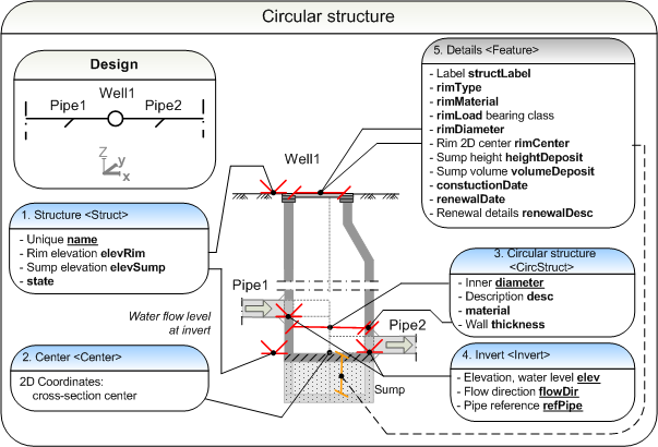
8.5.1 Circular structures
Inspection wells of French drains are an example of a circular structure. Circular structures are defined using the structure element <Struct> and its child elements.
The figure below illustrates the representation of a drain well, including a sump. The sump is defined in the extension "IM_struct" by defining the sump height and volume.
|
|
<Struct> |
short example |
8.5.1.1 General data
The name of the structure, the rim top elevation elevRim, elevation of the elevSump and state state. All structural elements in the file are assigned unique names.
Attributes of a structure <Struct>:
|
name |
unique name |
e.g. [Well1] |
|
desc |
structure description
|
e.g.[inspection well] |
|
elevRim |
elevation of rim, top surface
|
[elevation] |
|
elevSump |
elevation of the bottom at the outlet invert level
|
[elevation] |
|
oID |
object ID number |
unique identifier in the file, e.g. [145] |
|
state |
state
|
[abandoned]
[destroyed]
[existing]
[proposed] |
|
|
<Struct> |
schema documentation |
|
|
<Struct> |
short example |
8.5.1.2 Center
The center of the cross-section at the bottom of the well or the sump is set by 2D coordinates, separated by spaces in the <Center> element.
<Center>northing easting</Center>
|
|
<Center> |
schema documentation |
|
|
<Center> |
short example |
8.5.1.3 Circular structure
The body diameter at the bottom of the well, the description desc, the
material and the thickness of the shell material. The well cone and sump are described in further detail in the extension "IM_struct"
Attributes of a <CircStruct>:
|
diameter |
inner diameter of well
|
in file diameter units, e.g. [0.800] |
|
desc |
description |
identifier, e.g. [inspection well, cone] |
|
material |
material |
e.g. [concrete], [unknown] |
|
thickness |
thickness |
in file distance units, e.g. [0.1] |
|
|
<CircStruct> |
schema documentation |
|
|
<CircStruct> |
short example |
8.5.1.4 Inverts
The adjoining inlet and outlet inverts are described using the element <Invert>. The required attributes of invert are: the elevation <elev> as the crown level for pressure pipes and the invert level for others, the flow direction <flowDir> and the pipe reference <refPipe>.
Attributes of an <Invert>:
|
elev |
elevation (crown or invert level)
|
[elevation] |
|
flowDir |
flow direction
|
inlet / outlet / both [in | out | both] |
|
refPipe |
pipe reference
|
e.g. [Pipe1] |
|
|
<Invert> |
schema documentation |
|
|
<Invert> |
short example |
8.5.1.5 Details
It is optional to present additional information of the inframodel file transfer. the structure may be labeled by a structLabel. The additional information for the rim encompasses the rimType and the rim load bearing class rimLoad. When describing a conical well the diameter describes the diameter of the bottom of the cone. The rimDiameter describes the inner diameter of the rim and the rimCenter defines the 2D coordinates of the rim center. The description of the sump contains a description of the depth of the sump heightDeposit and the volume of the sump, volumeDeposit. The dates of different actions may also be defined, suct as the constructionDate and the renewalDate.
The dates of the actions are typically give in years. It is also possible to describe the renewal in further detail, e.g. the method used, using the renowalDesc attribute.
"IM_struct" <Feature>
|
name |
optional name |
[13] |
|
code |
code |
[IM_struct] |
|
source |
source
|
[inframodel] |
|
label |
[structLabel] |
structure label
|
value |
e.g. [123] |
|
label |
[rimType] |
rim type
|
value |
alternatives include [solid cover | grate | atrium grate | side inlet | drain cap ] |
|
label |
[rimMaterial] |
rim material
|
value |
alternatives include [ stainless steel | concrete] |
|
label |
[rimLoad] |
rim load bearing class
|
value |
alternatives include e.g. [250kN | 400kN] |
|
label |
[rimDiameter] |
diameter of the rim
|
value |
given in terms of file diameter units, e.g. [600] |
|
label |
[rimCenter] |
coordinates of the center of the rim
|
value |
[northing easting] |
|
label |
[heightDeposit] |
depth of the sump
|
value |
in terms of file height units
|
|
label |
[volumeDeposit] |
volume of the sump
|
value |
in terms of file volume units
|
|
label |
[constuctionDate] |
construction date
|
value |
[yyyy | yyyymm | yyyymmdd]. e.g.
[200512] |
|
label |
[renewalDate] |
renewal date
|
value |
[yyyy | yyyymm | yyyymmdd], e.g.
[2010] |
|
label |
[renewalDesc] |
renewal description, e.g. method
|
value |
e.g. [cleansing]
|
|
|
<Feature> |
schema documentation |
|
|
<Feature> |
short example |
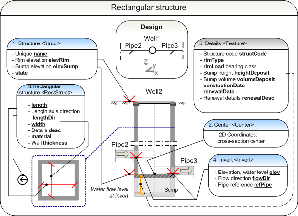
8.5.2 Rectangular structures
The illustration below describes the description method of a rectangular structure. The structure is defined using the <Struct> element and its child elements:
The illustration demonstrates the method of description of a rectangular well, including a sump as an example. The sump is defined by its depth and/or volume.
|
|
<Struct> |
short example |
8.5.2.1 General data
The general information contains the name, elevation of the top surface of the rim elevRimp, elevation of the bottom at the water level of the lower invert elevSump and the state of the structure. All elements are assigned unique names.
Attributes of a structure <Struct>:
|
name |
unique name |
e.g. [Well2] |
|
desc |
structure description
|
e.g.[inspection well] |
|
elevRim |
rim top elevation
|
[elevation] |
|
elevSump |
the elevation of the bottom at the water level of the lower invert
|
[elevation] |
|
oID |
object ID number |
unique identifier in the file, e.g. [146] |
|
state |
state
|
[abandoned]
[destroyed]
[existing]
[proposed] |
|
|
<Struct> |
schema documentation |
|
|
<Struct> |
short example |
8.5.2.2 Center
The center of the cross-section at the bottom of the well or the sump is set by 2D coordinates, separated by spaces in the <Center> element.
<Center>northing easting</Center>
|
|
<Center> |
schema documentation |
|
|
<Center> |
short example |
8.5.2.3 Rectangular Structure
The mandatory attributes of a rectangular structure are the length the direction of the long edge lenghtDir, the width of the short edge width, the material of the structure and the thickness of the surface structure.
Attributes of a rectangular structure <RectStruct>:
|
length |
length, long edge of the cross-section |
in file distance units, e.g. [0.800] |
|
lengthDir |
direction, long edge of the cross-section |
in file direction units, e.g. [0] |
|
width |
width, short edge of the cross-section |
in file width units, e.g. [0.800] |
|
desc |
description |
description, e.g. [inspection well, rectangular] |
|
material |
material |
e.g. [concrete], [unknown] |
|
thickness |
thickness |
in file distance units [0.1] |
|
|
<RectStruct> |
schema documentation |
|
|
<RectStruct> |
short example |
8.5.2.4 Inverts
The adjoining inlet and outlet inverts are described using the element <Invert>. The required attributes of invert are: the elevation <elev> as the crown level for pressure pipes and the invert level for others, the flow direction <flowDir> and the pipe reference <refPipe>.
Attributes of an <Invert>:
|
elev |
elevation (crown or invert level) |
[elevation] |
|
flowDir |
flow direction |
[in | out | both] |
|
refPipe |
pipe reference |
e.g. [Pipe2] |
|
|
<Invert> |
schema documentation |
|
|
<Invert> |
short example |
8.5.2.5 Details
It is optional to present additional information of the inframodel file transfer. the structure may be labeled by a structLabel. The additional information for the rim encompasses the rimType and the rim load bearing class rimLoad. The description of the sump contains a description of the depth of the sump heightDeposit and the volume of the sump, volumeDeposit. The dates of different actions may also be defined, suct as the constructionDate and the renewalDate.
The dates of the actions are typically give in years. It is also possible to describe the renewal in further detail, e.g. the method used, using the renowalDesc attribute.
"IM_struct" <Feature>
|
name |
optional name |
[14] |
|
code |
code |
[IM_struct] |
|
source |
source |
[inframodel] |
|
label |
[structLabel] |
structure label |
value |
e.g. [234] |
|
label |
[rimType] |
rim type |
value |
alternatives include [solid cover | grate | atrium grate | side inlet | drain cap ] |
|
label |
[rimMaterial] |
rim material
|
value |
alternatives include [ stainless steel | concrete] |
|
label |
[rimLoad] |
rim load bearing class |
value |
alternatives include [250kN | 400kN] |
|
label |
[heightDeposit] |
sump depth |
value |
in file height units |
|
label |
[volumeDeposit] |
sump volume |
value |
mittaunit statevuus |
|
label |
[constuctionDate] |
construction date |
value |
[yyyy | yyyymm | yyyymmdd]. e.g.
[200512] |
|
label |
[renewalDate] |
renewal date |
value |
[yyyy | yyyymm | yyyymmdd], e.g.
[2010] |
|
label |
[renewalDesc] |
renewal details, e.g. methods
|
value |
e.g. [scouring]
|
|
|
<Feature> |
schema documentation |
|
|
<Feature> |
short example |
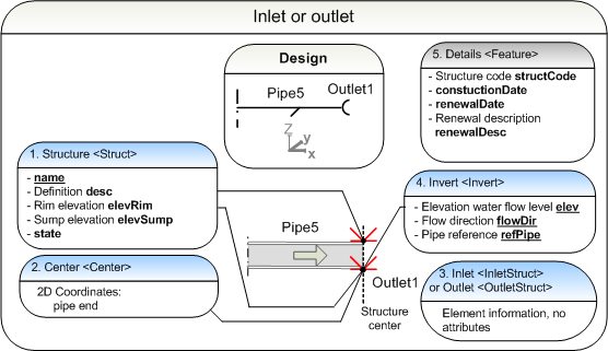
8.5.3 Pipe inlets and outlets
Pipe inlets and outlets are end of the pipe network pipes. The following illustration demonstrates the method of description. The virtual structures of the pipe ends are defined using the structure attribute <Struct> and its child elements:
The illustration below demonstrates how pipe inlets and outlets are described. The example demonstrates an outlet.
|
|
<Struct> |
short example |
8.5.3.1 General data
The name, elevation of the rim elevRim elevation of the sump elevSump and the state of the structure are mandatory attributes of an inlet or outlet structure. All structural elements in the file are assigned unique names.
Attributes of a Structure <Struct>:
|
name |
unique name |
e.g. [Outlet1] |
|
desc |
description |
e.g. [pipe end] |
|
elevRim |
rim elevation, top surface
|
[elevation] |
|
elevSump |
bottom elevation, bottom surface
|
[elevation] |
|
oID |
object ID number |
unique identifier in file, e.g. [147] |
|
state |
state |
[abandoned]
[destroyed]
[existing]
[proposed] |
|
|
<Struct> |
schema documentation |
|
|
<Struct> |
short example |
8.5.3.2 Center
The pipe end is defined by space-separated 2D-coordinates in the <Center> element.
<Center>northing easting</Center>
|
|
<Center> |
schema documentation |
|
|
<Center> |
short example |
8.5.3.3 Inlet or outlet
Inlets <InletStruct> and outlets
<OutletStruct> have no attributes.
|
|
<InletStruct> ja
<OutletStruct> |
short example |
8.5.3.4 Inverts
The inlet or outlet of a virtual structural element is described with the element <Invert>. The required attributes of an invert are: the elevation <elev> as the crown level for pressure pipes and the invert level for others, the flow direction <flowDir> and the pipe reference <refPipe>.
Attributes of an <Invert>:
|
elev |
elevation (crown or invert level) |
[elevation] |
|
flowDir |
flow direction |
[in | out | both] |
|
refPipe |
pipe reference |
e.g. [Pipe5] |
|
|
<Invert> |
schema documentation |
|
|
<Invert> |
short example |
8.5.3.5 Details
It is optional to define details in the inframodel file transfer. The structure can be identified by a label structLabel. Procedures carried out on the structure are defined by the constructionDate and the renewalDate. These are typically given in years. It is also possible to include a description of the renewal procedure, such as the method used, using the attribute renowalDesc.
"IM_struct" <Feature>
|
name |
optional name |
[15] |
|
code |
code |
[IM_struct] |
|
source |
source |
[inframodel] |
|
label |
[structLabel] |
structure label |
value |
e.g. [345] |
|
label |
[constuctionDate] |
construction date |
value |
[yyyy | yyyymm | yyyymmdd]. e.g.
[200512] |
|
label |
[renewalDate] |
renewal date |
value |
[yyyy | yyyymm | yyyymmdd], e.g.
[2010] |
|
label |
[renewalDesc] |
renewal information, e.g. methods |
value |
e.g. [scouring]
|
|
|
<Feature> |
schema documentation |
|
|
<Feature> |
short example |
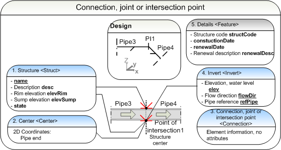
8.5.4 Pipe connections
Pipe connections, joints and points of intersection are defined by the <Connection> elements. The illustration bellow demonstrates the mode of description, which contains the attributes of the structure <Struct> and its child elements:
The illustration demonstrates the description method of a point of intersection.
When using the element to delimit a pipe network, the terminal drainage well is connected to a pipe that terminates in a <Connection> element. It is thus possible to also describe the connections of the outermost wells in the plan network. It is advisable to name the elements in a fashion that is clearly different from the rest of the plan, e.g. "Terminal1", "Terminal2".
|
|
<Struct> |
short example |
8.5.4.1 General data
The name, rim elevation elevRim, sump elevation
elevSump and the state of the structure are mandatory attributes. All structural elements in the file are assigned individual names.
When the element describes a delimiting element, all attributes are not used. The name of the structure and the description desc
are set to differ from the plan informatuion as much as possible e.g.
by naming them "Terminal1", "Terminal2". The elevation of the rim elevRim, the elevation of the sump elevSump and the state of the structure are left undefined.
Attributes of the element <Struct>:
|
name |
unique name |
e.g. [PI1] |
|
desc |
description |
alternatives include [tee fitting | bend fitting | repair socket | terminal], e.g.
[bend fitting 45 degrees] |
|
elevRim |
rim elevation, top |
[elevation] |
|
elevSump |
sump bottom elevation |
[elevation] |
|
oID |
object ID number |
unique identifier in file, e.g. [148] |
|
state |
state |
[abandoned]
[destroyed]
[existing]
[proposed] |
|
|
<Struct> |
schema documentation |
|
|
<Struct> |
short example |
8.5.4.2 Center
The <Center> of a connection, joint or point of intersection at the mounting level is set using space-separated 2D coordinates.
<Center>northing easting</Center>
|
|
<Center> |
schema documentation |
|
|
<Center> |
short example |
8.5.4.3 Connection
Connections, joints or points of intersection are defined using the <Connection> element, that has no attributes.
|
|
<Connection> |
short example |
8.5.4.4 Inverts
The inlet or outlet of a structural element is described with the element <Invert>. The required attributes of an invert are: the elevation <elev> as the crown level for pressure pipes and the invert level for others, the flow direction <flowDir> and the pipe reference <refPipe>.
<Invert> attributes:
|
elev |
elevation (crown or invert level) |
[elevation] |
|
flowDir |
flow direction |
[in | out | both] |
|
refPipe |
pipe reference |
e.g. [Pipe3] |
|
|
<Invert> |
schema documentation |
|
|
<Invert> |
short example |
8.5.4.5 Details
It is optional to define details in the inframodel file transfer. The structure can be identified by a label. Procedures carried out on the structure are defined by the
constructionDate and the renewalDate. These are typically given in years. It is also possible to include a description of the renewal procedure, such as the method used, using the attribute renowalDesc.
"IM_struct" <Feature>
|
name |
optional name |
[16] |
|
code |
code |
[IM_struct] |
|
source |
source |
[inframodel] |
|
label |
[structLabel] |
structure label |
value |
e.g. [456] |
|
label |
[constuctionDate] |
construction date |
value |
[yyyy | yyyymm | yyyymmdd]. e.g.
[200512] |
|
label |
[renewalDate] |
renewal date |
value |
[yyyy | yyyymm | yyyymmdd], e.g.
[2010] |
|
label |
[renewalDesc] |
renewal information, e.g. methods |
value |
e.g. [scouring]
|
|
|
<Feature> |
schema documentation |
|
|
<Feature> |
short example |
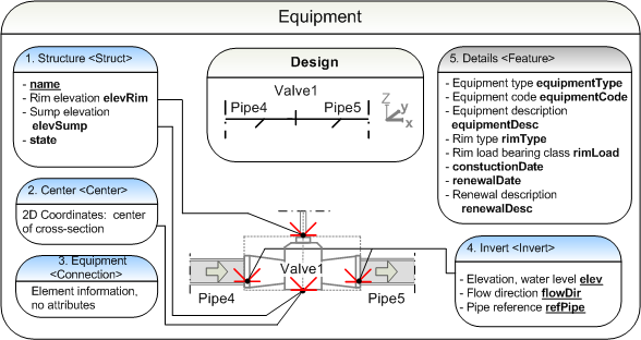
8.5.5 Equipment
Equipment is defined using the <Connection> element. The illustration bellow describes the mode of description of a structure <Struct> and its child elements:
The illustration demonstrates the mode of description of a valve:
|
|
<Struct> |
short example |
8.5.5.1 General data
The name, rim elevation elevRim, sump elevation elevSump and the state of the structure are mandatory attributes. All structural elements in the file are assigned individual names.
Attributes of a structure <Struct>:
|
name |
unique name |
e.g. [Valve1] |
|
elevRim |
Top elevation |
[elevation] |
|
elevSump |
Bottom elevation |
[elevation] |
|
oID |
object ID number |
unique identifier in file, e.g. [149] |
|
state |
state |
[abandoned]
[destroyed]
[existing]
[proposed] |
|
|
<Struct> |
schema documentation |
|
|
<Struct> |
short example |
8.5.5.2 Center
The <Center> of a piece of equipment at the mounting level is set using space-separated 2D coordinates.
<Center>northing easting</Center>
|
|
<Center> |
schema documentation |
|
|
<Center> |
short example |
8.5.5.3 Connection
A piece of equipment is defined using the element <Connection>, that has no attributes. Details of the equipment is defined in the extension "IM_struct".
|
|
<Connection> |
short example |
8.5.5.4 Inverts
The inlet or outlet of a structural element is described with the
element <Invert>. The required attributes of an invert are: the elevation <elev> as the crown level for pressure pipes and the invert level for others, the flow direction <flowDir> and the pipe reference <refPipe>.
<Invert> attributes:
|
elev |
elevation (crown or invert level) |
[elevation] |
|
flowDir |
flow direction |
[in | out | both] |
|
refPipe |
pipe reference |
e.g. [Pipe4] |
|
|
<Invert> |
schema documentation |
|
|
<Invert> |
short example |
8.5.5.5 Details
It is optional to define details in the inframodel file transfer. It is possible to define more detailed type information of a piece of equipment between two pipes, e.g. a Valve using the attributes equipmentType, equipmentCode and an equipment description equipmentDesc. The rim is defined by the rim type rimType and rim load bearing class rimLoad. Procedures carried out on the equipment are defined by the constructionDate and the renewalDate. These are typically given in years. It is also possible to include a description of the renewal procedure, such as the method used, using the attribute renewalDesc.
"IM_struct" <Feature>
|
name |
optional name |
[17] |
|
code |
code |
[IM_struct] |
|
source |
source |
[inframodel] |
|
label |
[equipmentType] |
equipment type
|
value |
alternatives include [Valve | Fire hydrant | Water hydrant], e.g.
[Valve] |
|
label |
[equipmentCode] |
equipment code
|
value |
e.g. [678] |
|
label |
[equipmentDesc] |
equipment description
|
value |
e.g. [CheckValve] |
|
label |
[rimType] |
rim type |
value |
alternatives include [solid cover | grate | atrium grate | side inlet | drain cap ] |
|
label |
[rimMaterial] |
rim material
|
value |
alternatives include [ stainless steel | concrete] |
|
label |
[rimLoad] |
rim load bearing class |
value |
alternatives include [250kN | 400kN] |
|
label |
[constuctionDate] |
construction date |
value |
[yyyy | yyyymm | yyyymmdd]. e.g.
[200512] |
|
label |
[renewalDate] |
renewal date |
value |
[yyyy | yyyymm | yyyymmdd], e.g.
[2010] |
|
label |
[renewalDesc] |
renewal information, e.g. methods |
value |
e.g. [scouring]
|
|
|
<Feature> |
schema documentation |
|
|
<Feature> |
short example |
8.6 Pipes
The topological network consists of different kinds of structures, whose exact location is given. The pipes that compose the <PipeNetwork> are described as a structure collection <Pipes> that has no attributes. A <Pipe> is defined between two structure nodes <Struct> by refering to them in the start- and end-attributions.
NOTE: In the special case of "network" where there is only one single pipe (such as a culvert with no specified connection at either end), the referenced start and end structure shall be <InletStruct> and <OutletStruct>, respectively.
Available pipe types in the LandXML standard:
Using a pipe to delimit a pipe network is a special case that is described separately for each pipe type.
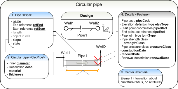
8.6.1 Circular pipes
The following illustation descibes the definition of a round pipe The definition employs the element <Pipe> and its child elements.
|
|
<Pipe> |
short example |
8.6.1.1 Pipe
The name, end reference refEnd, start reference refStart, slope and state are mandatory attributes. Setting the exact length of a pipe is optional. All pipe elements are assigned unique names.
When using a pipe to delimit a pipe network the pipe is given a name that clearly distinguishes it from other content in the file, e.g. "Terminal1". The name, end reference refEnd and start reference refStart are the only mandatory attributes. The other attributes are not set.
Attributes of a <Pipe>:
|
name |
unique name |
e.g. [Pipe1] |
|
refEnd |
end reference |
e.g. [Well2] |
|
refStart |
start reference |
e.g. [Well1] |
|
length |
exact length of a pipe |
in file distance units |
|
oID |
object ID number |
unique identifier in file, e.g. [150] |
|
slope |
slope |
unit % |
|
state |
state |
[abandoned]
[destroyed]
[existing]
[proposed] |
|
|
<Pipe> |
schema documentation |
|
|
<Pipe> |
short example |
8.6.1.2 Circular pipe
The diameter, type description desc, material and wall thickness of the pipe are mandatory attributes.
When defining a network-limiting pipe the diameter is the only defined attribute. Other attributes are not defined.
Attributes of a Circular pipe <CircPipe>:
|
diameter |
diameter |
in file diameter units |
|
desc |
description |
e.g. [250 SN8] |
|
material |
material |
alternatives include [concrete | pvc | pe | pel | peh | pem | pp | sg], e.g. [pvc] |
|
thickness |
thickness |
in file distance units |
|
|
<CircPipe> |
schema documentation |
|
|
<CircPipe> |
short example |
8.6.1.3 Center
The pipe curvature is defined by space-separated 3D-coordinates in the <Center> element.
<Center>northing easting elevation</Center>
|
|
<Center> |
schema documentation |
8.6.1.4 Details
It is optional to define details in inframodel file transfers. The label of pipe can be given using a pipeLabel. The start and end coordinates of a pipe are defined by three parameters: 1) elevation type elevType 2) start coordinate pipeStart and the 3) end coordinate pipeEnd. The jointType sets the type of joints and connections used for
the pipe. When the defined pipe is a pressurized sewer the pressureClass of the pipe is defined. Procedure details are defined with the constructionDate and renewalDate. It is also possible to define detailed information of the renewal using the renewal description renewalDesc, e.g. the method used to renew the pipe.
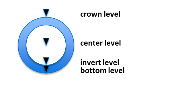
When the start and end coordinates are given with elevation values, elevation type shall be given as one of the enumerated elevTypes shown below.
"IM_pipe" <Feature>
|
name |
optional name |
[18] |
|
code |
code |
[IM_pipe] |
|
source |
source |
[inframodel] |
|
label |
[pipeLabel] |
pipe label |
value |
e.g. [12345] |
|
label |
[elevType] |
elevation type |
value |
[crown level | center level | invert level | bottom level] |
|
label |
[pipeStart] |
start coordinates |
value |
[northing easting elevation] |
|
label |
[pipeEnd] |
end coordinates |
value |
[northing easting elevation] |
|
label |
[jointType] |
joint type |
value |
alternatives include [rubber seal | flange | connector | weld],
e.g. [rubber seal] |
|
label |
[pressureClass] |
pipe pressure class |
value |
agreed on by the plan parties, according to pipe utilization pressure |
|
label |
[constuctionDate] |
construction date |
value |
[yyyy | yyyymm | yyyymmdd]. e.g.
[200512] |
|
label |
[renewalDate] |
renewal date |
value |
[yyyy | yyyymm | yyyymmdd], e.g.
[2010] |
|
label |
[renewalDesc] |
renewal information, e.g. methods |
value |
e.g. [scouring]
|
|
|
<Feature> |
schema documentation |
|
|
<Feature> |
short example |
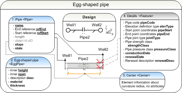
8.6.2 Egg pipes
The following illustation descibes the definition of an egg-shaped pipe The definition employs the element <Pipe> and its child elements.
Illustration of egg-shaped pipe represenation.
|
|
<Pipe> |
short example |
8.6.2.1 Pipe
The name, end reference refEnd, start reference refStart, slope and state are mandatory attributes. Setting the exact length of a pipe is optional. All pipe elements are assigned unique names.
When using a pipe to delimit a pipe network the pipe is given a name that clearly distinguishes it from other content in the file, e.g. "Terminal1". The end reference refEnd start reference refStart are the only mandatory attributes. The other attributes are not set.
Attributes of a <Pipe>:
|
name |
unique name |
e.g. [Pipe2] |
|
refEnd |
end reference |
e.g. [Well2] |
|
refStart |
start reference |
e.g. [Well1] |
|
length |
exact length of a pipe |
in file distance units |
|
oID |
object ID number |
unique identifier in file, e.g.
[150] |
|
slope |
slope |
unit % |
|
state |
state |
[abandoned]
[destroyed]
[existing]
[proposed] |
|
|
<Pipe> |
schema documentation |
|
|
<Pipe> |
short example |
8.6.2.2 Egg pipe
Mandatory attributes are height
height, width span, type description desc, material material and pipe thickness thickness.
When defininga network-limiting pipe the height
height and width span are set. Other attributes are not set.
Egg pipe <EggPipe> attributes:
|
height |
height |
in file height units |
|
span |
width |
in file width units |
|
desc |
description |
e.g. [250/200 SN8 MUNA] |
|
material |
material |
alternatives include [concrete | pvc | pe | pel | peh |
pem | pp | sg], e.g. [pvc] |
|
thickness |
thickness |
in file distance units |
|
|
<EggPipe> |
schema documentation |
|
|
<EggPipe> |
short example |
8.6.2.3 Center
The pipe curvature is defined by space-separated 3D-coordinates in the <Center> element.
<Center>northing easting elevation</Center>
|
|
<Center> |
schema documentation |
8.6.2.4 Details
It is optional to define details in inframodel file transfers. The label of pipe can be given using a pipeLabel. The start and end coordinates of a pipe are defined by three parameters: 1) elevation type elevType 2) start coordinate pipeStart and the 3) end coordinate pipeEnd. The jointType sets the type of joints and connections used for the pipe. When the defined pipe is a pressurized sewer the pressureClass of the pipe is defined. Procedure details are defined with the constructionDate and renewalDate. It is also possible to define detailed information of the renewal using the renewal description renewalDesc, e.g. the method used to renew the pipe.
When start and end coordinates are defined, elevation type shall be given as one of the elevTypes illustrated for circular pipes (8.6.1), center being at the level where the cross section is the widest.
"IM_pipe" <Feature>
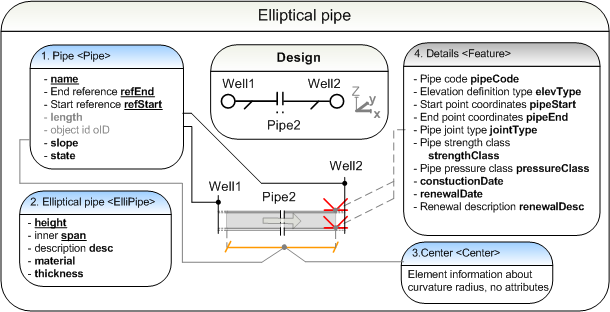
8.6.3 Elliptic pipes
The following illustation descibes the definition of an elliptical pipe. The definition employs the element <Pipe> and its child elements.
|
|
<Pipe> |
short example |
8.6.3.1 Pipe
The name, end reference refEnd, start reference refStart, slope and state are mandatory attributes. Setting the exact length of a pipe is optional. All pipe elements are assigned unique names.
When using a pipe to delimit a pipe network the pipe is given a name that clearly distinguishes it from other content in the file, e.g. "Terminal1". The end reference refEnd start reference refStart are the only mandatory attributes. The other attributes are not set.
Attributes of a <Pipe>:
|
name |
unique name |
e.g. [Pipe2] |
|
refEnd |
end reference |
e.g. [Well2] |
|
refStart |
start reference |
e.g. [Well1] |
|
length |
exact length of a pipe |
in file distance units |
|
oID |
object ID number |
unique identifier in file, e.g. [151] |
|
slope |
slope |
unit % |
|
state |
state |
[abandoned]
[destroyed]
[existing]
[proposed] |
|
|
<Pipe> |
schema documentation |
|
|
<Pipe> |
short example |
8.6.3.2 Elliptic pipe
Mandatory attributes are pipe section height
height, width span, pipe type description desc, material material and pipe thickness thickness.
When defining a network mandatory attributes are height height ja width span. Other attributes are not set.
elliptical pipe <ElliPipe> attributes:
|
height |
height, interal |
in file height units |
|
span |
width, internal |
in file width units |
|
desc |
description |
e.g. [250/200 SN8 SOIKEA] |
|
material |
material |
alternatives include [concrete | pvc | pe | pel | peh | pem | pp | sg], e.g. [pvc] |
|
thickness |
thickness |
in file distance units |
|
|
<ElliPipe> |
schema documentation |
|
|
<ElliPipe> |
short example |
8.6.3.3 Center
The pipe curvature is defined by space-separated 3D-coordinates in the <Center> element.
<Center>northing easting elevation</Center>
|
|
<Center> |
schema documentation |
8.6.3.4 Details
It is optional to define details in inframodel file transfers. The label of pipe can be given using a pipeLabel. The start and end coordinates of a pipe are defined by three parameters: 1) elevation type elevType 2) start coordinate pipeStart and the 3) end coordinate pipeEnd. The jointType sets the type of joints and connections used for the pipe. When the defined pipe is a pressurized sewer the pressureClass of the pipe is defined. Procedure details are defined with the constructionDate and renewalDate. It is also possible to
define detailed information of the renewal using the renewal description renewalDesc, e.g. the method used to renew the pipe.
When start and end coordinates are defined, elevation type shall be given as one of the elevTypes illustrated for circular pipes (8.6.1).
"IM_pipe" <Feature>
|
name |
optional name |
[20] |
|
code |
code |
[IM_pipe] |
|
source |
source |
[inframodel] |
|
label |
[pipeLabel] |
pipe label |
value |
e.g. [23456] |
|
label |
[elevType] |
elevation type |
value |
[crown level | center level | invert level | bottom level] |
|
label |
[pipeStart] |
start coordinates |
value |
[northing easting elevation] |
|
label |
[pipeEnd] |
end coordinates |
value |
[northing easting elevation] |
|
label |
[jointType] |
pipe joint type |
value |
e.g. [rubber seal | flange | connector | weld],
e.g. [rubber seal] |
|
label |
[pressureClass] |
pipe pressure class |
value |
Agreed on by plan parties
|
|
label |
[constuctionDate] |
construction date |
value |
[yyyy | yyyymm | yyyymmdd]. e.g.
[200512] |
|
label |
[renewalDate] |
renewal date |
value |
[yyyy | yyyymm | yyyymmdd], e.g.
[2010] |
|
label |
[renewalDesc] |
renewal information, e.g. methods |
value |
e.g. [scouring]
|
|
|
<Feature> |
schema documentation |
|
|
<Feature> |
short example |
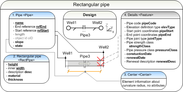
8.6.4 Rectangular pipes
The following illustation descibes the definition of a rectangular
pipe. The definition employs the element <Pipe> and its
child elements.
|
|
<Pipe> |
short example |
8.6.4.1 Pipe
The name, end reference refEnd, start reference refStart, slope and state are mandatory attributes. Setting the exact length of a pipe is optional. All pipe elements are assigned unique names.
When using a pipe to delimit a pipe network the pipe is given a name that clearly distinguishes it from other content in the file, e.g. "Terminal1". The end reference refEnd start reference refStart are the only mandatory attributes. The other attributes are not set.
Attributes of a <Pipe>:
|
name |
unique name |
e.g. [Pipe3] |
|
refEnd |
end reference |
e.g. [Well2] |
|
refStart |
start reference |
e.g. [Well1] |
|
length |
exact length of a pipe |
in file distance units |
|
oID |
object ID number |
unique identifier in file, e.g. [152] |
|
slope |
slope |
unit % |
|
state |
state |
[abandoned]
[destroyed]
[existing]
[proposed] |
|
|
<Pipe> |
schema documentation |
|
|
<Pipe> |
short example |
8.6.4.2 Rectangular pipe
The pipe height height, width width, description desc, material ja pipe thickness.
When defining a network-limiting pipe the height and width are mandatory attributes. Other attributes are not set.
Attributes of a rectangular pipe. <RectPipe>:
|
height |
height, internal |
in file height units |
|
width |
width, internal |
in file width units |
|
desc |
description |
e.g. [250/200 SN8] |
|
material |
material |
alternatives include [concrete | pvc | pe | pel | peh | pem | pp | sg], e.g. [pvc] |
|
thickness |
thickness |
in file distance units |
|
|
<RectPipe> |
schema documentation |
|
|
<RectPipe> |
short example |
8.6.4.3 Center
The pipe curvature is defined by space-separated 3D-coordinates in the <Center> element.
<Center>northing easting elevation</Center>
|
|
<Center> |
schema documentation |
8.6.4.4 Details
It is optional to define details in inframodel file transfers. The label of pipe can be given using a pipeLabel. The start and end coordinates of a pipe are defined by three parameters: 1) elevation type elevType 2) start coordinate pipeStart and the 3) end coordinate pipeEnd. The jointType sets the type of joints and connections used for the pipe. When the defined pipe is a pressurized sewer the pressureClass of the pipe is defined. Procedure details are defined with the constructionDate and renewalDate. It is also possible to
define detailed information of the renewal using the renewal description renewalDesc, e.g. the method used to renew the pipe.
When start and end coordinates are defined, elevation type shall be given as one of the elevTypes illustrated for circular pipes (8.6.1).
"IM_pipe" <Feature>
|
name |
optional name |
[21] |
|
code |
code |
[IM_pipe] |
|
source |
source |
[inframodel] |
|
label |
[pipeLabel] |
pipe label |
value |
e.g. [34567] |
|
label |
[elevType] |
elevation type |
value |
[crown level | center level | invert level | bottom level] |
|
label |
[pipeStart] |
start coordinates |
value |
[northing easting elevation] |
|
label |
[pipeEnd] |
end coordinates |
value |
[northing easting elevation] |
|
label |
[jointType] |
pipe joint type |
value |
alternatives include [rubber seal | flange | connector | weld],
e.g. [rubber seal] |
|
label |
[pressureClass] |
pipe pressure class |
value |
agreed on by the plan parties, according to pipe utilization pressure |
|
label |
[constuctionDate] |
construction date |
value |
[yyyy | yyyymm | yyyymmdd]. e.g.
[200512] |
|
label |
[renewalDate] |
renewal date |
value |
[yyyy | yyyymm | yyyymmdd], e.g.
[2010] |
|
label |
[renewalDesc] |
renewal information, e.g. methods |
value |
e.g. [scouring]
|
|
|
<Feature> |
schema documentation |
|
|
<Feature> |
short example |
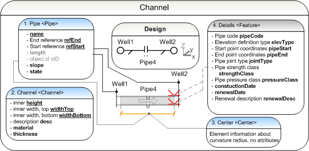
8.6.5 channel
The following illustation descibes the definition of a channel pipe. The definition employs the element <Pipe> and its
child elements.
Illustration of channel description:
|
|
<Pipe> |
short example |
8.6.5.1 Pipe
The name, end reference refEnd, start reference refStart, slope and state are mandatory attributes. Setting the exact length of a pipe is optional. All pipe elements are assigned unique names.
When using a pipe to delimit a pipe network the pipe is given a name that clearly distinguishes it from other content in the file, e.g. "Terminal1". The end reference refEnd start reference refStart are the only mandatory attributes. The other attributes are not set.
Attributes of a <Pipe>:
|
name |
unique name |
e.g. [Pipe4] |
|
refEnd |
end reference |
e.g. [Well2] |
|
refStart |
start reference |
e.g. [Well1] |
|
length |
exact length of a pipe |
in file distance units |
|
oID |
object ID number |
unique identifier in file, e.g. [153] |
|
slope |
slope |
unit % |
|
state |
state |
[abandoned]
[destroyed]
[existing]
[proposed] |
|
|
<Pipe> |
schema documentation |
|
|
<Pipe> |
short example |
8.6.5.2 channel
Mandatory attributes are channel section height height, top width widthTop, bottom width widthBottom, pipe type description desc, material material ja thickness thickness.
When defining a network mandatory attributes are height height, top width widthTop and bottom width widthBottom. Other attributes are not set.
channel <Channel> attributes:
|
height |
height, internal |
in file height units |
|
widthTop |
top width, inside |
in file width units |
|
widthBottom |
bottom width, inside |
in file width units |
|
desc |
description |
e.g. [250/250-100 SN8] |
|
material |
material |
alternatives include [concrete | pvc | pe | pel | peh | pem | pp | sg], e.g. [pvc] |
|
thickness |
thickness |
in file distance units |
|
|
<Channel> |
schema documentation |
|
|
<Channel> |
short example |
8.6.5.3 Center
The pipe curvature is defined by space-separated 3D-coordinates in the <Center> element.
<Center>northing easting elevation</Center>
|
|
<Center> |
schema documentation |
8.6.5.4 Details
It is optional to define details in inframodel file transfers. The label of pipe can be given using a pipeLabel. The start and end coordinates of a pipe are defined by three parameters: 1) elevation type elevType 2) start coordinate pipeStart and the 3) end coordinate pipeEnd. The jointType sets the type of joints and connections used for the pipe. Procedure details are defined with the constructionDate and renewalDate. It is also possible to define detailed information of the renewal using the renewal description renewalDesc, e.g. the method used to renew the pipe.
"IM_pipe" <Feature>
|
name |
optional name |
[22] |
|
code |
code |
[IM_pipe] |
|
source |
source |
[inframodel] |
|
label |
[pipeLabel] |
pipe label |
value |
e.g. [45678] |
|
label |
[elevType] |
elevation type |
value |
[crown level | invert level | bottom level] |
|
label |
[pipeStart] |
start coordinates |
value |
[northing easting elevation] |
|
label |
[pipeEnd] |
end coordinates |
value |
[northing easting elevation] |
|
label |
[jointType] |
pipe joint type |
value |
alternatives include [rubber seal | flange | connector | weld],
e.g. [rubber seal] |
|
label |
[constuctionDate] |
construction date |
value |
[yyyy | yyyymm | yyyymmdd]. e.g.
[200512] |
|
label |
[renewalDate] |
renewal date |
value |
[yyyy | yyyymm | yyyymmdd], e.g.
[2010] |
|
label |
[renewalDesc] |
renewal information, e.g. methods |
value |
e.g. [scouring]
|
|
|
<Feature> |
schema documentation |
|
|
<Feature> |
short example |