Mandatory /
 Optional Elements

type coding system(s)
type coding breakline
type coding random points
typecoding surface
plan information
|
Mandatory /
Optional Elements |
||||||||
|---|---|---|---|---|---|---|---|---|
|
<LandXML> | Transfer file | ||||||
|
<Units><Metric> | Units (Metric) | ||||||
|
<CoordinateSystem> | Coordinate and elevation system | ||||||
|
<Start> | Base point | ||||||
|
<Project> | Project | ||||||
|
<Feature> | "bSI_codings" extension type coding system(s) | ||||||
|
<Application> | Application | ||||||
|
<Author> | Authors | ||||||
|
<Surfaces> | Surface group | ||||||
|
<Surface> | Surface | ||||||
|
<SourceData> | Source Data | ||||||
|
<Breaklines> | Breakline group | ||||||
|
<Breakline> | Breakline | ||||||
|
<PointList3D> | 3D point list | ||||||
|
<Feature> | "bSI_coding" extension type coding breakline | ||||||
|
<DataPoints> | Random points | ||||||
|
<PntList3D> | 3D point list | ||||||
|
<Feature> | "bSI_coding" extension type coding random points | ||||||
|
<Definition> | Surface description | ||||||
|
<Pnts> | Vertices | ||||||
|
<P> | Vertex | ||||||
|
<Faces> | Faces | ||||||
|
<F> | Face | ||||||
|
<Feature> | "bSI_coding" extension typecoding surface | ||||||
|
<Feature> | "bSI_plan" extension plan information | ||||||
|
<FeatureDictionary> | Extension definition dictionary | ||||||
The base data contains the following concepts:
 visible (terrain) and layered (strata) surfaces, existing or planned
random points
breaklines
plan information
type coding
The random points and breaklines represent the source data used in creation of the mesh surfaces. The surface description contains the vertex points used to form the surface faces; breaklines are not used to define surfaces.
All project information may be presented in one single exchange file (theoretically), but in practical situations most likely will be divided into appropriate packages. In particular, in cases where the content is composed of parts employing different
coordinate or unit systems, these parts should be exchanged in separate files.
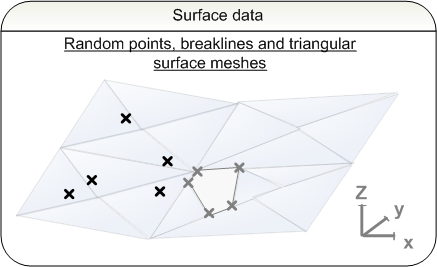
Surfaces and source data is described as surface groups <Surfaces>, which are made of individual <Surface>-elements. The names of surface groups and the names of surfaces within the same group are unique.
Attributes of the surface group <Surfaces>:
 |
desc | description | e.g. [surface model] |
 |
name | unique name | e.g. [example surfaces] |
|
state | state |
[abandoned] [destroyed] [existing] [proposed] |
Attributes of the <Surface> element:
|
name | name, unique in surface group | e.g. [ground surface] |
|
desc | description |
e.g. [contains triangle mesh, breaklines and random points] |
|
OID | object ID number | individual identifier in the file, e.g. [15] |
|
state | state |
[abandoned] [destroyed] [existing] [proposed] |
For the surface description the project is divided into surface groups <Surfaces> with optional bSI_plan extension. If the project consists of
sub-projects that have different rates of progress, the plan contents
of the file are divided into sub-projects according to the same division. The plan information contains the planName, planCode, the planState and the plan description planDesc. The plan state is described according to a scheme agreed on by the parties of the project.
Plan information bSI_plan <Feature>
|
name | Optional name |
e.g. [2] | ||
|
code | Mandatory feature code |
[bSI_plan] | ||
|
source | reference to source feature distionary by name |
[bSI_LandMVD] | ||
| plan attributes <Property> | |||||
|
label | [planName] | plan name |
value | e.g. [Plan1] |
|
label | [planCode] | plan code | value | e.g. [12345-321] |
|
label | [planState] | plan state | value | Categories agreed on by parties of the projects, e.g. [zoning | project planning | implementation plan | construction plan | use and maintenance | removal] |
|
label | [planDesc] | description of the plan |
value | additional information, e.g. [Zone1] |
An existing surface is defined by setting the state of the <Surface> element to "existing". If it is proposed the state is set to "proposed". If all the surfaces within a surface group have the same state, it is possible to set the state on a higher level in the surface group <Surfaces>. The state for an individual surface is set if the constituent triangle meshes, random points and breaklines are is the same state.
The type coding systems are declared under <Project> element as part of the header information, see section 1.6 Codings. Type codes can be set for individual plan elements:
in the element <DataPoints> for random points in the element <BreakLine> for breaklines in the element
<Surface> for surfaces
Individual type codes are set primarily in parent elements, from which the child elements will inherit the values. It is possible to assign multiple type codes to a particular element if parallel coding systems are in use. E.g. the primary type codes for terrain points and breaklines might come from a terrain coding system, but additionally codes from a surface coding system might also apply. Each code from a particular system is assigned using an instance of "bSI_coding" <Feature> element, where the code and its label (or verbal description) are given in <Property> elements. The given code value is identified with a coding system by the unique name given when declaring the coding system under <Project> element: the system name is used as a prefix to the code value, with a colon (':') as separator.
bSI_coding
<Feature>
|
name | optional name |
e.g. [3] | ||
|
code | mandatory feature code |
[bSI_coding] | ||
|
source | reference to source feature distionary by name |
[bSI_LandMVD] | ||
| typecodes <Property> | |||||
|
label | [coding] | assigned code |
value | system name:code, e.g. [TIEL:0] |
|
label | [codingDesc] | label or description of the assigned code |
value | e.g. [terrain point or breakline] |
The source data is described by the element <SourceData>. This element has no attributes.
Source data consists of:
Random points <DataPoints> and Breaklines
<BreakLines>
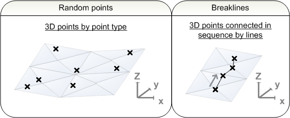
Random points are described by the element <DataPoints>,
sorting every point group into individual elements. Their attributes are:
|
name | name | [name of point group] |
|
state | state |
[abandoned] [destroyed] [existing] [proposed] |
The point group is classified by bSI_coding. The individual random points in the <DataPoints> point group are presented as a 3D coordinate list in the <PntList3D> element, values separated by spaces
<PntList3D>northing1 easting1 elevation1 northing2 easting2 elevation2...</PntList3D>
In the breakline group <BreakLines>, each <BreakLine> is presented in its own elemen. The breakline group has no attributes. The breakline type brkType defines the use in software.
Attributes of an individual <BreakLine>:
|
brkType | breakline type | [standard] [wall] [proximity] [nondestructive] |
|
desc | description | |
|
name | optional name |
|
|
state | state |
[abandoned] [destroyed] [existing] [proposed] |
Breaklines are classified by bSI_coding and they can be given individual names. The constituent points of a <BreakLine> are described as a 3D coordinate list in the <PntList3D> element, values separated by spaces
<PntList3D>northing1 easting1 elevation1 northing2 easting2 elevation2..></PntList3D>
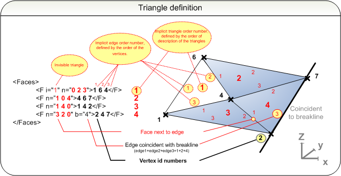
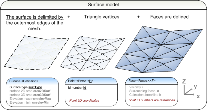
Surface geometry is described as triangulated meshes. Each surface is defined under the <Definition> in terms of boundaries, exterior features and holes. A triangular mesh is defined in two steps; first by defining the vertices of the triangular faces as surface points, and then each individual face by three vertices. The surface points used as vertices are assigned unique identifiers id within the same surface definition (<Surface>.<Definition>) element. The face definitions are done by referring to the id numbers id of the vertice points.
All triangulated mesh surfaces shall be continuous, and should have convex shape, padded with invisible triangles (faces with attribute i=1) where needed.
Additionally, the surface is given an type code according to the declared bSI_coding.
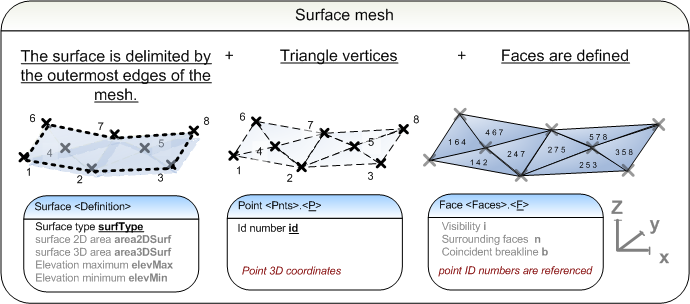
The surface type surfType is set to "TIN" when describing a triangular mesh. The presicion of the mesh model depends on the available software and data. It is possible to optionally describe a 2D surface area area2DSurf, 3D surface area area3DSurf and the maximum elevation elevMax and minimum elevation elevMin.
Attributes of the <Definition>:
|
surfType | surface type |
[TIN | grid] |
|
area2DSurf | 2D surface area |
in surface area units, e.g. [2450.510000] |
|
area3DSurf | 3D surface area | in surface area units, e.g. [2450.510000] |
|
elevMax | elevation maximum |
elevation, e.g. [64.372000] |
|
elevMin | elevation minimum |
elevation, e.g. [56.431000] |
The vertex point group <Pnts> contains a listing of individual vertices <P>, which are each assigned an individual id number id. These numbers are referenced in the triangulation.
Attribute of vertex <P>:
|
id | unique integer number | e.g. [1] [2] [3] etc. |
The vertices of a surface definition, minimum three of them, are given as <P> elements, where the 3D coordinates are separated by spaces.
<P id="1">northing1 easting1 elevation1</P>
<P id="2">northing2 easting2 elevation2</P>
<P
id="3">northing3 easting3 elevation3</P>
The triangulation is defined in the <Faces> collection. It consists of consecutive list of faces <F>. The order of the faces implicitly defines the index number of each triangle (1,2,..). Each face is defined by a list of three vertex id numbers. All triangles of a TIN surface must have same direction (vertices listed either clockwise or counter-clockwise, not mixed).
Optional attributes of faces <F>:
|
i | visibility | [1] = part of the triangulation, but not visible, i.e. not representing any physical part of surface, but e.g. a hole |
|
n | surrounding faces |
defines in terms of integer numbers if there is a face adjascent to the face described [0] = no faces adjacent [implicit index number of face] = defines which faces share a common edge e.g. [0 2 3] = edge1 (no face), edge 2 (face 2), edge 3 (face 3) |
|
b | coinsidence with breakline |
Sum value indicating which edges touch breakline (value 0-7): edge 1 = 1 edge 2 = 2 edge 3 = 4 e.g. value 4 = only edge 3 touches breakline |
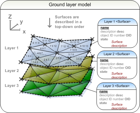
The surface model contains a description of the topmost structural
surface. It consists of the vertices of the component faces <Pnts> and the faces <Faces>
that they form. It is possible to assign
random points and breaklines to the surface. The type code defines the
purpose of the surface. A surface is part of the plan (bSI_plan).
The ground layer model contains a description of all the structural surfaces in the plan. It is recommended that surfaces are described
top-down. Individual structural layer surfaces are constructed similarly to the surface model. The plan element is the parent element
of the ground layer model.
NOTE: ground layer model may be used for calculating volumes between individual layers, but rules for such calcaluations are subject to further agreement (volume model not implied here).